DIY Spod- Waytekwire

I have gathered the components to build the spod. One question I have is what is behind the advise you give "If you will not be adding an accessory yet for accessory 5, don’t install the relay or fuse."
Thanks, Scot
 
I have gathered the components to build the spod. One question I have is what is behind the advise you give "If you will not be adding an accessory yet for accessory 5, don’t install the relay or fuse."
Thanks, Scot

Not sure about all of that. I have all relays in mine and only use one currently. I just shift the fuse off a space so it doesn't have power out when the relay turns on. I'm probably going to mod a few so they only can be turned on with the key
 
I ran mine with the fuse and relay connected for about a year. Just make sure the out to component wire is properly protected so if you do hit the switch it does not arc.
 
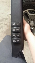
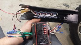
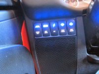
I finally got around to installing this weekend. Turned out great! I use CAD at work, so I quickly mapped everything out beforehand. That ended up saving a bunch of time.

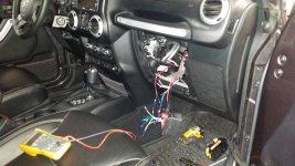
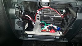
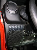
For the unused circuits I left everything active. That way when the times come to install, all I have to do is plug in the 2 quick disconnects. One for the power and one for the ground. For grounds I used an extra 8ga terminal that I used for the main bus...then made up 5 short wires with female quick disconnects. I wanted everything hidden, so I mounted the Bussman panel in the space below the glove box. Left all the wires about a foot longer so I could pull the panel to quickly access everything.

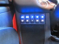
I used switched power for the text side of the switches. When I'm at a campground or dark trail I sometimes do not want to turn on my lights to see the switch...mostly for wildlife. This way the switch lights up with only the key. Since I normally drive with my running lights on anyway it wasn't a big deal for me.

Light Wiring Diagram (B&W).jpg
switch panel.jpg
panel wiring.jpg
dash wiring.jpg
dash wiring 2.jpg
 
I finally got around to installing this weekend. Turned out great! I use CAD at work, so I quickly mapped everything out beforehand. That ended up saving a bunch of time.

For the unused circuits I left everything active. That way when the times come to install, all I have to do is plug in the 2 quick disconnects. One for the power and one for the ground. For grounds I used an extra 8ga terminal that I used for the main bus...then made up 5 short wires with female quick disconnects. I wanted everything hidden, so I mounted the Bussman panel in the space below the glove box. Left all the wires about a foot longer so I could pull the panel to quickly access everything.

I used switched power for the text side of the switches. When I'm at a campground or dark trail I sometimes do not want to turn on my lights to see the switch...mostly for wildlife. This way the switch lights up with only the key. Since I normally drive with my running lights on anyway it wasn't a big deal for me.

Looks Great! Did the switches come from OTRATTW? I have the same switch panel somewhere in my garage and I'm in need of horizontal switches like yours.
 
Looks Great! Did the switches come from OTRATTW? I have the same switch panel somewhere in my garage and I'm in need of horizontal switches like yours.

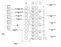
Thanks! The switches did come from OTRATTW. When you select the switch you want, there's a drop down for the horizontal switch option. I used the factory A-pillar cover and cut it up. The Daystar panel leaves a weird gap at the bottom on the newer interiors...which I don't like.
 
^ nice job on the switch panel Clint! :thumb:
The switches he used all have led lights that will turn on when the switch is on.

And for those that know up front that they will need more than 5 relays/circuits for their setup- Cooper Bussman does make a 10 relay/40 fuse panel $57.57

http://www.waytekwire.com/item/46357/RFRM-FUSE-RELAY-2-88-MM-NO/

Has anyone pulled the trigger on the 10 relay panel yet? This one is labeled as No BUS which I would assume means no power BUS bar and you will need to run individual power to each relay (which would suck/be a mess). The DUAL BUS http://www.waytekwire.com/item/46354/RFRM-FUSE-RELAY-2-88-MM-DUAL/ runs $81.

pvan, does this sound correct. You are the the resident wirehead..... :yup:

Looking to expand and considering consolidation to one panel and re purposing my original panel on my 2009 JKU.

I've been planning on using the Dual Bus 10 relay for a while. One bus with be Acc+ the other will be constant power, I'll ground a 3rd bus elsewhere. This set up will give all kinds of flexibility. 100a constant, 100a Acc, 10 relays and 40 fuses. Should never need more.
 
I've been planning on using the Dual Bus 10 relay for a while. One bus with be Acc+ the other will be constant power, I'll ground a 3rd bus elsewhere. This set up will give all kinds of flexibility. 100a constant, 100a Acc, 10 relays and 40 fuses. Should never need more.

That's exactly what I was thinking of as well. I was wondering how the bus terminal were configured and what the approximate size is. I just installed the ARB Twin compressor in the engine bay on the M.O.R.E. bracket and there looks to be a perfect place for the 10 relay panel. I guess I will have to be the guinea pig..... :D
 
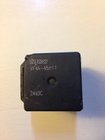
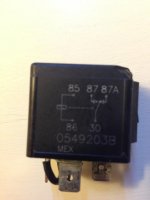
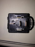
I found a box of these Tyco Relays. If I clip the Jumper from 85 to 86 will I be able to use these?

What would you be using this for?
Also, the coil on the ones you have is rated for 24vdc. You need them to be 12vdc
 
Sorry I don't know how I forgot to ask the actual question at hand but it was in regards to the 24VDC. Now not being very electrical literate I will take it that being that majority of my accessories are 12v that these 24v will be to much?

And I have read the thread, I am just wanting to ensure that other then the soldered jumper that there is nothing internally different about these 24v Relays.

Its not that it is too much, it won't work in the system, the coil of the relay requires 24v to turn it on, you only have 12v in your jeep, you need 12vdc relays.
 
That bracket mount used to mount the Bussman relay look good what is the Catalog number to find it on the website :thinking:

MOUNTING BRACKET ATO / ATC & RTMR FUSE BLOCKS
Item #: 46085
Manufacturer Item: B028-7012-0-J
Manufacturer: Cooper Bussmann Eaton
Available: 951.00
$4.3485
EACH
Quantity:

Add To Cart
Price Break for UM: EA
Quantity Price
10+ 3.6900
50+
 
MOUNTING BRACKET ATO / ATC & RTMR FUSE BLOCKS
Item #: 46085
Manufacturer Item: B028-7012-0-J
Manufacturer: Cooper Bussmann Eaton
Available: 951.00
$4.3485
EACH
Quantity:

Add To Cart
Price Break for UM: EA
QuantityPrice
10+3.6900
50+

Thanks bro
 
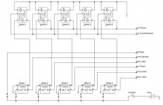
Thanks a lot to this thread. Without it I would have had an outcome much inferior to what I ended up with. Here are a few pics of my version along with my wiring diagram using 2 LED Carling rocker switches.


diy%u00252Bspod.jpg

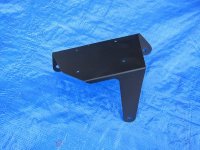
The bracket my dad made for me. :)
IMG_1666.jpg

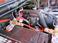
50A breaker mounted to the battery box.
IMG_1707.jpg

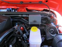
Relay box mounted above brake booster.
IMG_1708.jpg

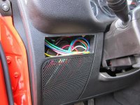
A little surgery on the dash.
IMG_1665.jpg

5 switch bezel

IMG_1718.jpg
 

Attachments

  • IMG_1715.JPG
    IMG_1715.JPG
    153 KB · Views: 260
  • IMG_1719.jpg
    IMG_1719.jpg
    107.5 KB · Views: 224
Last edited:
Top Bottom