Oso Build Thread

Hey Dave, did you get the drag link flip kit from EVO? If so, the bracket interferes with the PSC bracket. When I asked Eddie and EVO how they make it work together, they both said "just weld on some tabs", which didn't come close to being a satisfying answer for me. I've torn the steering apart on my last jeep, and when stuff doesn't go right, it's a huge headache. So I want to make sure I know EXACTLY how to attach it BEFORE I start tearing things apart. Haha. So if you could snap some photos and do a little write up I would GREATLY appreciate it. Thanks brother!
 
Ha I agree! I did get the flip kit. I'm hoping we can steal the mounting points from the PSC mounting bracket. Might know more later today or tomorrow.
 
Ha I agree! I did get the flip kit. I'm hoping we can steal the mounting points from the PSC mounting bracket. Might know more later today or tomorrow.

Ok cool! The more pictures the better, please. Got a guy that is sourcing the individual parts for the PSC setup, and it will be $750 with a new pump and everything... Way cheaper than buying it as a kit from PSC, Northridge, etc...
 
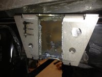
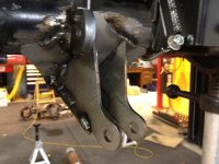
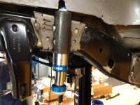
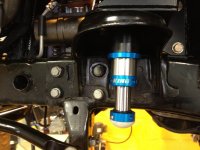
Back to the front coilover (CO) mounts for a second. The instructions say to slide the bottom plate/ring through the bump stop, align it with the existing 1/2" hole, center it around the bump stop and mark the two 7/16" holes. Then drill those holes and install the CO mount by cutting the plastic above as necessary.

It is subtle, but I recommend the following sequence:
  1. Temporarily mount the CO bracket using the 1/2" bolt (no nut)
  2. Swing the CO bracket around and do the necessary plastic cutting above for clearance
  3. Cut enough plastic ribs away to get the bracket swung into position and lined up with the two upper holes in the stock shock mount
  4. Add the bottom plate around the bump stop
  5. Add the nut to the existing 1/2" bolt above the bump stop and begin tightening
  6. Add a 1/2" nut and bolt to the lower hole in the stock shock mount
  7. Using these two bolts as your positioning guide, tighten them up. At the same time position the bottom ring centered around the bump stop
  8. Now drill one of the two 7/16" holes. You can check your alignment using the butt end of two drill bits; one above in the CO mount and one from below in the bottom ring
  9. Install the bolt for the new hole (this eliminates the possibility of accidentally twisting the bottom ring while drilling)
  10. Drill the second hole and install the bolt

This sequence ensures the CO mount is in just the right position for all the bolts to line up. It's not the EVO brackets that vary... It's the Jeep!

Use these two bolts for positioning the bracket in #7 above. Then drill for the other bolts:
2013-02-01 13.33.27 CO bolts.jpg
 
Last edited:
I am finally at the point of putting stuff on instead of cutting stuff off! :thumb:

I won't duplicate what is over in the PSC thread I started, but if you have questions about installing the PSC ram assist on a 2012+, then that thread may help:
PSC-Steering-Assist-2013-and-CAI-system

Here is what's been done:
  • PSC steering pump, reservoir and gearbox installed
  • F/R housings back from getting 4.88 gears installed
  • Front coilover upper mounts installed
  • Front high clearance control arm brackets in place waiting to be welded
  • Rear coilover upper mounts installed
  • Rear trackbar relocation complete (still needs to be welded)
  • Rear high clearance control arms tacked in place at the axle
  • Rear high clearance control arm bracket at frame end in place

Next steps:
  • Position and tack in place the rear lower shock mounts
  • Figure out the mounting points for the PSC ram
  • Install front lower shock mounts
  • Mount the front axle and connect all steering components
  • Install new axle shafts
  • Mount front and rear drive shafts
  • Check everything for fitment
  • Trim pinch seams
  • Install the rock skins
  • Tack in place the rock sliders
  • Get the welder over to finish everything up
  • Paint
  • Tighten everything up
  • Fenders
  • ???
Here are some pictures.
Rear high clearance bracket. Note I just threw up the control arms; I eventually swapped them so the adjustable end is at the axle.
IMG_0424.jpg

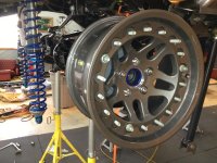
Threw up a wheel to check East / West position of the axle
IMG_0428.jpg

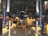
View of our temporary setup
IMG_0429.jpg

Bump stop extension and factory upper CA mount (what Eddie just broke :( )
IMG_0432.jpg

Still gotta drill the frame hole for the upper CA's
IMG_0433.jpg

Lower CA mount ready to be tacked in place
IMG_0434.jpg

Tacked in; should have cut that part of the old bracket off first. Looks like crap.
IMG_0438.jpg
 
No they will stay black. Bumpers, sliders, skins, fenders, top and tires black. Wheels and body silver.
 
Finally making some progress.

The suspension and gussets are all ready to be welded. Everything is tacked in place for tomorrow morning at 9am when Dale Jr. shows up to do the welding.

Cut outs for rear bump stops. This was a bit unnerving. Very deep cuts in the frame!
IMG_0440.jpg

Rear lower control arm and shock mounts tacked in place:
IMG_0447.jpg

Rear bump stop tacked in place:
IMG_0454.jpg

Front bump stops installed:
IMG_0455.jpg
 
Welding done! Oh that feels good. Now clean up some splatter, paint and put back together!

Actually it is not quite done. Rock sliders have to be done yet and we also have to figure out flipping the exhaust loop. But all the suspension is done!

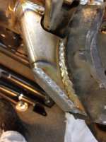
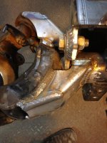
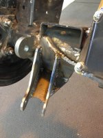
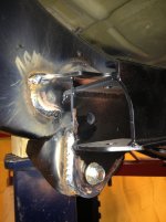
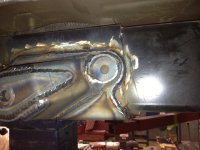
Two photos of the axle gussets:
IMG_0472.jpg

IMG_0464.jpg

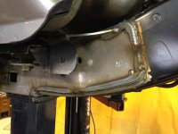
Front half of the rear pass high clearance bracket
IMG_0479.jpg

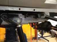
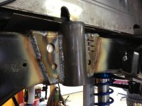
Pass side rear lower control arm mount
IMG_0473.jpg

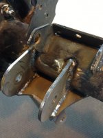
Driver side rear lower shock mount
IMG_0474.jpg

Back half of the rear driver high clearance bracket
IMG_0471.jpg

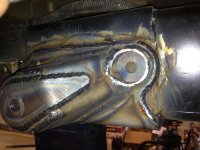
Driver side rear bump stop
IMG_0470.jpg

Back half of the rear passenger high clearance bracket
IMG_0466.jpg

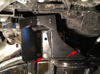
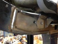
Front pass control arm bracket
IMG_0465.jpg
 

Attachments

  • IMG_0468.jpg
    IMG_0468.jpg
    107.2 KB · Views: 504
Last edited:
Top Bottom