Samuelh3
Caught the Bug
I just recently purchased and installed one of the first few production SFZ Air Command systems and I gotta say I'm really impressed. For all you tech geeks out there, you'll love the integration with your smart devices and being able to not only control air up/down, but also see stats regarding how long it takes. Being that this is one of the first few systems released, there were no instructions so I worked with Steve from Strike Force Zebra to get it installed. I figured I'd do a write-up as everyone's setup may be slightly different and I thought it's about time I gave back to this community.
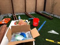
As luck would have it. I got the package in the middle of a backyard project so I couldn't get started right away. Packaging was very secure and had everything you need including all the tubing and fittings.
First step is always the most nerve racking as it typically includes drilling holes into sheet metal so its a one way street. I started on the rear wheels as any mistake could easily be hidden. I used a drill punch tool, then a small drill bit (9/16) to get the hole started, followed by a stepped drill but and worked my way up to 13/16. Make sure you sand and paint to edges to deburr and prevent any rust.
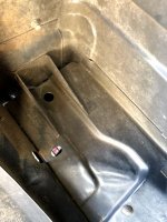
I chose this location so as to make hide and protect the inlet at much as possible. Its about an inch or so down from the edge as it provides room on the driver side to still get a socket in under the fuel breather valve when you go to tighten the quick connect air inlet. I also like the subtle look so you can't tell its there.
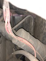
Once drilled, I sanded and painted the holes at attached the Quick connect Air inlets picture here with the whip attached. (I believe you have the option to get red or blue whips. I went with blue to match my coilovers, but I think Red airs up and down faster )
)
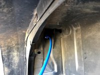
Once complete with the rear I moved to the front. I have the EVO Full Liners so depending on what you're running your setup may be different. If you are running EVO liners, I located the hole about an inch under the top self tapping screw. This should clear the sheet metal so you're only drilling into the Liner.
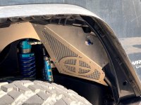
Next step was running the supplied black hose to the various locations. Again, I wanted to go with a subtle "hidden" look so I went thru the frame. This probably took the most amount of time as fishing it thru the frame and around various bolts was a bit challenging. I started here on the passenger to keep the hose away from the muffler as recommended by Steve from SFZ (pictured with connections already inserted) and used the holes along the frame to pull the hose out and back into the frame being careful not to kink the hose as I fed it back into the frame. I found looping it back in to form a circle seemed to work.
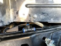
I exited the frame at a hole on top of the frame near one of the body mounts.
(Pic to be added later)
Once I got enough hose to get to the general vicinity of the front wheel I came back to the rear and made my first cut to the hose making sure to cut it as straight and clean as possible and connected it to the first T- Fitting just past the rear crossmember near the diff breather hose. I plan to drill two small holes and tuck the T-fitting up behind the sheet metal to keep it hidden and from rattling around.
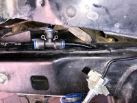
I drilled a hole into the bottom of the plastic cover leading into the rear break light assembly area doing my best to avoid the insulation foam.
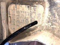
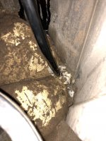
After which I connected the rear wheel fitting and started working my way across the rear crossmember, which was pretty straight forward. I brought it up along the gas filler tune and make my third hose cut on the passenger side once I had enough hose to reach the driver side rear wheel fitting.
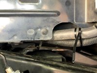
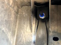
Working my way back to the front passenger side, I connected the T-fitting to the Quick Connect inlet as shown and started feeding more tubing from the wheel well up behind the battery and across the engine compartment along the rear wire harness loom and down to the driver side front tire.
(Pic to be added of T- Connection)
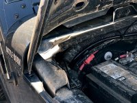
Once I cut the hose and made my connections to the quick connect and the tube running from the passenger side, I started from inside the cab and push the hose through the firewall and made the connection to the T-Fitting. You may not be able to see clearly in the picture but there's two hoses going through the firewall. One for the connections to the tire and the other for the airsource.
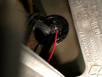
Once this connection was made I cut the hose with plenty of room to go under the driver's seat. Then ran a second hose through the firewall as pictured above for the air source. and connected to the available port on my ARB compressor, being sure to use the supplied silicone heat sheath for the tubing connected at the compressor. Note how the silicon sheath is completely covering the connector. Not sure if this is required but its how I say it depicted on the pictures I got from SFZ.
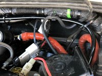
This completes the hoses routing and installation. I tightened up most of the lines up and used zip ties to secure everything and to keep it from rubbing.
The connection of the command unit was a breeze and all of the connections are clearly labeled. I used a common ground next to the door stop on the drivers side and rand the remaining wire through the firewall and onto my switch management system using the same switch as my compressor. The hose connections and wiring harness were pretty idiot proof.
Once all setup, you can download the SIMBLEE app from the app store, switch on the compressor and connect to the unit via the app. The default passcode is 7777 and the interface is pretty intuitive.
Huge shout out to Steve over at Strike Force Zebra for walking me through everything and patiently answering my 101 questions.
Whew!! That's my longest post ever. Mad respect to those that have done a write up before. Hope this helps.
As luck would have it. I got the package in the middle of a backyard project so I couldn't get started right away. Packaging was very secure and had everything you need including all the tubing and fittings.

First step is always the most nerve racking as it typically includes drilling holes into sheet metal so its a one way street. I started on the rear wheels as any mistake could easily be hidden. I used a drill punch tool, then a small drill bit (9/16) to get the hole started, followed by a stepped drill but and worked my way up to 13/16. Make sure you sand and paint to edges to deburr and prevent any rust.

I chose this location so as to make hide and protect the inlet at much as possible. Its about an inch or so down from the edge as it provides room on the driver side to still get a socket in under the fuel breather valve when you go to tighten the quick connect air inlet. I also like the subtle look so you can't tell its there.

Once drilled, I sanded and painted the holes at attached the Quick connect Air inlets picture here with the whip attached. (I believe you have the option to get red or blue whips. I went with blue to match my coilovers, but I think Red airs up and down faster

Once complete with the rear I moved to the front. I have the EVO Full Liners so depending on what you're running your setup may be different. If you are running EVO liners, I located the hole about an inch under the top self tapping screw. This should clear the sheet metal so you're only drilling into the Liner.

Next step was running the supplied black hose to the various locations. Again, I wanted to go with a subtle "hidden" look so I went thru the frame. This probably took the most amount of time as fishing it thru the frame and around various bolts was a bit challenging. I started here on the passenger to keep the hose away from the muffler as recommended by Steve from SFZ (pictured with connections already inserted) and used the holes along the frame to pull the hose out and back into the frame being careful not to kink the hose as I fed it back into the frame. I found looping it back in to form a circle seemed to work.

I exited the frame at a hole on top of the frame near one of the body mounts.
(Pic to be added later)
Once I got enough hose to get to the general vicinity of the front wheel I came back to the rear and made my first cut to the hose making sure to cut it as straight and clean as possible and connected it to the first T- Fitting just past the rear crossmember near the diff breather hose. I plan to drill two small holes and tuck the T-fitting up behind the sheet metal to keep it hidden and from rattling around.

I drilled a hole into the bottom of the plastic cover leading into the rear break light assembly area doing my best to avoid the insulation foam.


After which I connected the rear wheel fitting and started working my way across the rear crossmember, which was pretty straight forward. I brought it up along the gas filler tune and make my third hose cut on the passenger side once I had enough hose to reach the driver side rear wheel fitting.


Working my way back to the front passenger side, I connected the T-fitting to the Quick Connect inlet as shown and started feeding more tubing from the wheel well up behind the battery and across the engine compartment along the rear wire harness loom and down to the driver side front tire.
(Pic to be added of T- Connection)

Once I cut the hose and made my connections to the quick connect and the tube running from the passenger side, I started from inside the cab and push the hose through the firewall and made the connection to the T-Fitting. You may not be able to see clearly in the picture but there's two hoses going through the firewall. One for the connections to the tire and the other for the airsource.

Once this connection was made I cut the hose with plenty of room to go under the driver's seat. Then ran a second hose through the firewall as pictured above for the air source. and connected to the available port on my ARB compressor, being sure to use the supplied silicone heat sheath for the tubing connected at the compressor. Note how the silicon sheath is completely covering the connector. Not sure if this is required but its how I say it depicted on the pictures I got from SFZ.

This completes the hoses routing and installation. I tightened up most of the lines up and used zip ties to secure everything and to keep it from rubbing.
The connection of the command unit was a breeze and all of the connections are clearly labeled. I used a common ground next to the door stop on the drivers side and rand the remaining wire through the firewall and onto my switch management system using the same switch as my compressor. The hose connections and wiring harness were pretty idiot proof.
Once all setup, you can download the SIMBLEE app from the app store, switch on the compressor and connect to the unit via the app. The default passcode is 7777 and the interface is pretty intuitive.
Huge shout out to Steve over at Strike Force Zebra for walking me through everything and patiently answering my 101 questions.
Whew!! That's my longest post ever. Mad respect to those that have done a write up before. Hope this helps.
Last edited:
